<?xml version="1.0" encoding="utf-8"?>
<feed xmlns="http://www.w3.org/2005/Atom" xmlns:dc="http://purl.org/dc/elements/1.1/" xmlns:thr="http://purl.org/syndication/thread/1.0">
    <title>RADIO KITS IN JA　: トランジスタ式AMトランスミッター。　トランスレス変調typeⅢ</title>
    <link rel="self" type="application/atom+xml" href="http://www.radiokits.jp/radio_kit_/mic_tr_3/atom.xml" />
    <link rel="alternate" type="text/html" href="http://www.radiokits.jp/radio_kit_/" />
    
    <id>tag:app.dcnblog.jp,2003:weblog-358158</id>
    <updated>2018-03-28T00:38:00+09:00</updated>
    <subtitle>信州安曇野発アナログラジオ工作中心blogです。ラジオ自作派にお手伝い用基板１、基板2、基板3、基板4を領布中
 6Z-DH3Aのヒーターピンは必ず1番を接地。間抜けは6番ピンを接地する　　6Z-DH3Aのピン　接続情報 　amazon等での転売shopが多数ありますが、私とは無関係です。騙されぬようにご注意ください。トランジスタラジオキット,真空管短波ラジオ、真空管レフレックスラジオ、AMワイヤレスマイク、FMワイヤレスマイク、12AU7ダイレクトコンバージョン製作。LC7265ラジオ周波数表示器、ミニワッター、トランジスタアンプ、スピーカーの鳴る単球ラジオなど計 609例。 真空管ラジオ修理記やFMチューナー修理記など。20代は半導体ラジオ修理技術者でした。FA機械設計屋を35年やってます。画像多数にてPC推奨します。 資料画像等はお持ち帰りいただいてOKです。記事にする折には、ご一報ください。
since 2011/Aug</subtitle>
    <entry>
        <title>可変インダクターでアンテナマッチング。</title>
        <link rel="alternate" type="text/html" href="http://www.radiokits.jp/radio_kit_/2018/03/post-3.html" />
        <link rel="replies" type="text/html" href="http://www.radiokits.jp/radio_kit_/2018/03/post-3.html" thr:count="0" />
        <id>tag:app.dcnblog.jp,2003:post-58421721</id>
        <published>2018-03-28T00:38:00+09:00</published>
        <updated>2018-03-29T09:06:56+09:00</updated>
        <summary>****************************** MC1496AMト...</summary>
        <author>
            <name>takinx</name>
        </author>
        <category scheme="http://www.sixapart.com/ns/types#category" term="トランジスタ式AMトランスミッター。　トランスレス変調typeⅢ" />
        <category scheme="http://www.sixapart.com/ns/types#category" term="トランジスタ式AMトランスミッター。トランスレス変調　typeⅡ" />
        <category scheme="http://www.sixapart.com/ns/types#category" term="トランスレス変調　中波AMトランスミッター(自作)。MC1496" />
        <category scheme="http://www.sixapart.com/ns/types#category" term="ラジオ工作のテクニック" />
        
        
<content type="html" xml:base="http://www.radiokits.jp/radio_kit_/">
<![CDATA[
<div xmlns="http://www.w3.org/1999/xhtml"><p></p>
<p></p>
<p></p>
<p>******************************</p>
<p>MC1496AMトランスミッター基板や7石式トランスミッター基板では、アンテナとのマッチング回路を載せてある。</p>
<p>単にパイマッチが載っているだけだが、中波でパイマッチングさせるにはそこそこインダクタンスが必要になる。具合良いのが下写真のようなインダクタンス容量になる。　このタイプのインダクターを載せるようにしてある。お持ちでない場合は固定インダクターを交換しながら具合よいものを選定することになる。</p>
<p>まだYAHOOでは流通しているので、探してみてください。</p>
<p><a href="http://takinx.dcnblog.jp/.shared/image.html?/photos/uncategorized/2018/03/27/091.jpg" onclick="window.open( this.href, '_blank', 'width=800,height=600,scrollbars=no,resizable=no,toolbar=no,directories=no,location=no,menubar=no,status=no,left=0,top=0' ); return false"><img class="asset  asset-image at-xid-photo-55646107" style="width: 300px; display: block;" title="091" src="http://takinx.dcnblog.jp/radio_kit_/images/2018/03/27/091.jpg" alt="091" /></a></p>
<p>固定インダクターだと整合がいま一つの事があるが、可変タイプならカバーできる。1970年代には多数出回っていたが、もう製造もされていない。</p>
<p>FMステレオもIC単体で済むのでMPXコイルも流通がない。　AFのTノッチ回路にはMPXコイルが具合よいし、ダイレクトコンバージョンでのLPFとして採用された事例もCQ誌にはある。</p></div>
]]>
</content>


    </entry>
    <entry>
        <title>泉弘志先生式のトランスレス変調(AM)。変調回路は往時の復活版。　トランスミッター基板領布中。　</title>
        <link rel="alternate" type="text/html" href="http://www.radiokits.jp/radio_kit_/2018/02/am-171a.html" />
        <link rel="replies" type="text/html" href="http://www.radiokits.jp/radio_kit_/2018/02/am-171a.html" thr:count="0" />
        <id>tag:app.dcnblog.jp,2003:post-58369157</id>
        <published>2018-02-09T09:52:17+09:00</published>
        <updated>2018-02-11T08:07:46+09:00</updated>
        <summary>**************************** AM変調項で　少し確認...</summary>
        <author>
            <name>takinx</name>
        </author>
        <category scheme="http://www.sixapart.com/ns/types#category" term="AM変調考" />
        <category scheme="http://www.sixapart.com/ns/types#category" term="トランジスタ式AMトランスミッター。　トランスレス変調typeⅢ" />
        <category scheme="http://www.sixapart.com/ns/types#category" term="トランジスタ式AMトランスミッター。トランスレス変調　typeⅡ" />
        
        
<content type="html" xml:base="http://www.radiokits.jp/radio_kit_/">
<![CDATA[
<div xmlns="http://www.w3.org/1999/xhtml"><p></p>
<p>****************************</p>
<p><a href="http://takinx.dcnblog.jp/radio_kit_/am-mod/" target="_blank" rel="noopener">AM変調項</a>で　少し確認をしてきてたが</p>
<p>「加算回路で生成されたもの」は、トランジスタラジオで受信できる。</p>
<p>オイラは数式にはかなり弱いのだが、　「AM変調には乗算回路がMUSTではない」、「加算回路による生成されたものでもラジオ受信できる」ことは実験で確認できる。</p>
<p>むしろトランジスタ構成による乗算回路でのAM変調実験はAM波形にならずのままで、実験はそこで停止中だ。シュミレーションソフトと現実の整合性は謎でもある。</p>
<p>「DBMの増幅度」をデータシート上で眺めていくと、一桁前半のdB値の数字が載っている。公知数字と実際とは乖離することが多いので、「測定するとマイナスゲインのDBM」が結構人気があるのでオイラ的にはけっこう驚く。</p>
<p>雑誌等の刊行本を信用しすぎることなく実測していくことをお薦めする。　</p>
<p>◇6石式AMトランスミッター基板(基板ナンバーRK-04)。　これは泉弘志先生の変調方式を大凡45年ぶり復活させたもの。</p>
<p><a href="http://takinx.dcnblog.jp/.shared/image.html?/photos/uncategorized/2018/02/09/015.jpg" onclick="window.open( this.href, '_blank', 'width=800,height=600,scrollbars=no,resizable=no,toolbar=no,directories=no,location=no,menubar=no,status=no,left=0,top=0' ); return false"><img class="asset  asset-image at-xid-photo-55544698" style="width: 300px; display: block;" title="015" src="http://takinx.dcnblog.jp/radio_kit_/images/2018/02/09/015.jpg" alt="015" /></a></p>
<p class="youtube"><img src="https://i.ytimg.com/vi/OsdROAHXVj0/default.jpg?w=425&amp;h=355&amp;player=1" alt="6石AMトランスミッター transmitter board.  amplitude  modulation." /> <br /> <a href="http://jp.youtube.com/watch?v=OsdROAHXVj0" target="_blank" class="title" rel="noopener">YouTube: 6石AMトランスミッター transmitter board. amplitude modulation.</a></p>
<p></p>
<p>◇真空管を12.6vで作動させたワイヤレスマイクをご紹介する。（基板ナンバーRK-09)</p>
<p></p>
<p class="youtube"><img src="https://i.ytimg.com/vi/k_v49Hx1sOg/default.jpg?w=425&amp;h=355&amp;player=1" alt="12.6Vで動作する真空管ワイヤレスマイク" /> <br /> <a href="http://jp.youtube.com/watch?v=k_v49Hx1sOg" target="_blank" class="title" rel="noopener">YouTube: 12.6Vで動作する真空管ワイヤレスマイク</a></p>
<p></p>
<p>&nbsp;</p>
<p><a href="http://takinx.dcnblog.jp/.shared/image.html?/photos/uncategorized/2018/02/10/026.jpg" onclick="window.open( this.href, '_blank', 'width=800,height=600,scrollbars=no,resizable=no,toolbar=no,directories=no,location=no,menubar=no,status=no,left=0,top=0' ); return false"><img class="asset  asset-image at-xid-photo-55546888" style="width: 300px; display: block;" title="026" src="http://takinx.dcnblog.jp/radio_kit_/images/2018/02/10/026.jpg" alt="026" /></a></p>
<p></p>
<p>****************************************************</p>
<p>◇7石式AMトランスミッター基板(基板ナンバー　RK-06)。上記の6石にbufferを追加して飛び向上を図ったもの。ver1は「ＬＣ同調負荷⇒パイマッチング回路」としたら飛びすぎた.</p>
<p></p>
<p><a href="http://takinx.dcnblog.jp/.shared/image.html?/photos/uncategorized/2018/02/09/017_2.jpg" onclick="window.open( this.href, '_blank', 'width=800,height=600,scrollbars=no,resizable=no,toolbar=no,directories=no,location=no,menubar=no,status=no,left=0,top=0' ); return false"><img class="asset  asset-image at-xid-photo-55545861" style="width: 300px; display: block;" title="017_2" src="http://takinx.dcnblog.jp/radio_kit_/images/2018/02/09/017_2.jpg" alt="017_2" /></a></p>
<p></p>
<p>◇それで、終段負荷をHFトランシーバー同様に「RFC負荷⇒パイマッチング回路」に興して飛びを抑えた。</p>
<p>下写真のようにRFC負荷だ。Ver1.1になる。(基板ナンバー RK-06）</p>
<p><a href="http://takinx.dcnblog.jp/.shared/image.html?/photos/uncategorized/2018/02/09/018.jpg" onclick="window.open( this.href, '_blank', 'width=800,height=600,scrollbars=no,resizable=no,toolbar=no,directories=no,location=no,menubar=no,status=no,left=0,top=0' ); return false"><img class="asset  asset-image at-xid-photo-55545865" style="width: 300px; display: block;" title="018" src="http://takinx.dcnblog.jp/radio_kit_/images/2018/02/09/018.jpg" alt="018" /></a></p>
<p>飛びはアンテナマッチング次第になる。　飛び過ぎは非合法になってしまうので、飛び過ぎはお薦めできない。パイマッチのLC値は、アンテナ線長に支配されるが、パイマッチ計算には幾つかの考え方があるので、よく調べて正しいと想う考え方で答えを求めることをお薦めする。（パイマッチについては充分には挙動解析されていないとも云える）</p>
<p>マッチング部の実装なしでもそこそこ飛ぶので、「ラジオ製作⇒ワイヤレスマイク製作」の王道に進めると想う。</p>
<p>、、と、RK-06の領布を始めます。　廻り込み対策に「FB(6穴)」と「CRによるLPF」をMIC回路に乗せてある。</p>
<p>***********************************</p>
<p>ST管の再生式ラジオを製作してみたい方の参考にどうぞ。</p>
<p></p>
<p class="youtube"><img src="https://i.ytimg.com/vi/3kzOijxjVzA/default.jpg?w=425&amp;h=355&amp;player=1" alt="再生式はいぶりっどラジオ　1-V-2  デジタル表示" /> <br /> <a href="http://jp.youtube.com/watch?v=3kzOijxjVzA" target="_blank" class="title" rel="noopener">YouTube: 再生式はいぶりっどラジオ　1-V-2 デジタル表示</a></p>
<p></p></div>
]]>
</content>


    </entry>
    <entry>
        <title>LA1600 ラジオ基板(初回試作)。 同調回路でのコンデンサーQ大小を看る。</title>
        <link rel="alternate" type="text/html" href="http://www.radiokits.jp/radio_kit_/2018/01/sanyo-la1600-q-e9f6.html" />
        <link rel="replies" type="text/html" href="http://www.radiokits.jp/radio_kit_/2018/01/sanyo-la1600-q-e9f6.html" thr:count="0" />
        <id>tag:app.dcnblog.jp,2003:post-58347035</id>
        <published>2018-01-21T18:44:55+09:00</published>
        <updated>2018-05-03T16:21:36+09:00</updated>
        <summary>************************** LCR回路でQが重要なこと...</summary>
        <author>
            <name>takinx</name>
        </author>
        <category scheme="http://www.sixapart.com/ns/types#category" term="7MHz  自作短波ラジオ(LA1600) +BFO回路　：基板領布中" />
        <category scheme="http://www.sixapart.com/ns/types#category" term="トランジスタ式100kcマーカー　ver2(発振器)" />
        <category scheme="http://www.sixapart.com/ns/types#category" term="トランジスタ式455kHzマーカー製作(セラロック発振器)" />
        <category scheme="http://www.sixapart.com/ns/types#category" term="トランジスタ式AMトランスミッター。　トランスレス変調typeⅢ" />
        <category scheme="http://www.sixapart.com/ns/types#category" term="トランジスタ式AMトランスミッター。トランスレス変調　typeⅡ" />
        <category scheme="http://www.sixapart.com/ns/types#category" term="トランスレス変調　中波AMトランスミッター(自作)。MC1496" />
        
        
<content type="html" xml:base="http://www.radiokits.jp/radio_kit_/">
<![CDATA[
<div xmlns="http://www.w3.org/1999/xhtml"><p></p>
<p>**************************</p>
<p>LCR回路でQが重要なことは、よく知られている。オイラのSITEへ来られる方にとっては「常識の範囲」だろう。</p>
<p>試作中のLA1600基板がセパレートOSCしなかったので　実験を行なっていた。</p>
<p></p>
<p>OSCコイルを基板から剥がして、LA1600に直付けした。</p>
<p><a href="http://takinx.dcnblog.jp/.shared/image.html?/photos/uncategorized/2018/01/21/077.jpg" onclick="window.open( this.href, '_blank', 'width=800,height=600,scrollbars=no,resizable=no,toolbar=no,directories=no,location=no,menubar=no,status=no,left=0,top=0' ); return false"><img class="asset  asset-image at-xid-photo-55505558" style="width: 300px; display: block;" title="077" src="http://takinx.dcnblog.jp/radio_kit_/images/2018/01/21/077.jpg" alt="077" /></a></p>
<p>おお、波形がでた。　、、とオイラがパターンを間違えていることが判った。</p>
<p><a href="http://takinx.dcnblog.jp/.shared/image.html?/photos/uncategorized/2018/01/21/078.jpg" onclick="window.open( this.href, '_blank', 'width=800,height=600,scrollbars=no,resizable=no,toolbar=no,directories=no,location=no,menubar=no,status=no,left=0,top=0' ); return false"><img class="asset  asset-image at-xid-photo-55505560" style="width: 300px; display: block;" title="078" src="http://takinx.dcnblog.jp/radio_kit_/images/2018/01/21/078.jpg" alt="078" /></a></p>
<p>**************************************************</p>
<p>SELF OSCできたので、</p>
<p>次は、コンデンサーのジャケット素材(外装材)によってQの大小があるのか？</p>
<p>正確に云うと、「Q大小の判定に外観素材から推測できるか？」が出来ない　or 出来る？、、、。</p>
<p>コンデンサー製造装置の歴史を垣間みることになるが、現代に近い製造装置はエポキシジャケットが主流のようだ。その分、誘導体はわりと新しい素材が使われている。コンデンサー製造装置は結構長く使われており30年前、あるいは40年前のものも実働している。市場での部品単価が低く最新鋭設備の導入に踏み切れないことが主たる要因である。</p>
<p>ニチコンに、とある設備を設計製作し納入した折には、「脚付タンタル？のある製造工程」を内職に出していた。</p>
<p>製造メーカー名が多くの場合は不明だ。ジャケットで多少とも判断できるだろうか？</p>
<p>秋月さんではメーカー名を公知しているのでとても良心的だ。</p>
<p>
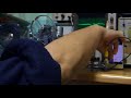
コイルのコアには手を触れず、コンデンサーだけつけかえてみた。</p>
<p>①　まずは、このジャケット品。 1.2V程度のOSC強度。</p>
<p>このジャケットはエポキシ系らしい。</p>
<p><a href="http://takinx.dcnblog.jp/.shared/image.html?/photos/uncategorized/2018/01/21/079.jpg" onclick="window.open( this.href, '_blank', 'width=800,height=600,scrollbars=no,resizable=no,toolbar=no,directories=no,location=no,menubar=no,status=no,left=0,top=0' ); return false"><img class="asset  asset-image at-xid-photo-55505567" style="width: 300px; display: block;" title="079" src="http://takinx.dcnblog.jp/radio_kit_/images/2018/01/21/079.jpg" alt="079" /></a></p>
<p>②　秋月で扱っているSupertech (5円/1個).</p>
<p>上よりやや弱い。　周波数がやや上なのでそれに起因するか？</p>
<p><a href="http://takinx.dcnblog.jp/.shared/image.html?/photos/uncategorized/2018/01/21/080.jpg" onclick="window.open( this.href, '_blank', 'width=800,height=600,scrollbars=no,resizable=no,toolbar=no,directories=no,location=no,menubar=no,status=no,left=0,top=0' ); return false"><img class="asset  asset-image at-xid-photo-55505575" style="width: 300px; display: block;" title="080" src="http://takinx.dcnblog.jp/radio_kit_/images/2018/01/21/080.jpg" alt="080" /></a></p>
<p>③　3番目にはこのジャケット品。(1円/1個)</p>
<p>さらにosc強度が弱い。　1.1v程度と　①に比べ1割弱い。</p>
<p><a href="http://takinx.dcnblog.jp/.shared/image.html?/photos/uncategorized/2018/01/21/081.jpg" onclick="window.open( this.href, '_blank', 'width=800,height=600,scrollbars=no,resizable=no,toolbar=no,directories=no,location=no,menubar=no,status=no,left=0,top=0' ); return false"><img class="asset  asset-image at-xid-photo-55505580" style="width: 300px; display: block;" title="081" src="http://takinx.dcnblog.jp/radio_kit_/images/2018/01/21/081.jpg" alt="081" /></a></p>
<p>*********************************</p>
<p>◇まとめ</p>
<p>上記のように市販コンデンサでのＱの大小が確認できた。こんなことを行なうのは、100kcマーカーの再現性に苦労したからだ。自作推奨siteではこのような事を行なっていないし、真空管ラジオ修理サイトではIFTのコンデンサー交換方法も公開しているが、そのコンデンサーのQについては述べていないのはやはり拙いだろう、、。と今回測定してみた。オシロでもQ大小は判る。 真空管用コンデンサーの<a href="http://takinx.dcnblog.jp/radio_kit_/2018/01/q-dd58.html">Q大小をみた</a>。</p>
<p>受信同調回路ではＱが高いと感度が高いことは大変よく知られている。それゆえに、わざわざ低いQ製品を使うことは避けようとする。エアバリコンを洗浄してQを復活させようと努力するのは、その現れだ。そのように、受信共振回路につかう部品はQを高めることに注力している。バリキャップでさえも高Qを強調して、「同調回路に使える」と公知している状態だ。左様に高Q部品が同調回路では求められている。</p>
<p>しかし、あえて低Q品を多用しコイルコア調整をブロードに換えることも出来る。その辺りは設計思想になってくる。ブロードにすることによりAM帯域内の垂れ下がりを低減し、HI-FI化する手法も真空管ラジオ時代から推奨されてきた。</p>
<p>HI-FI化するにあたり検波ラインとAGCラインがセパレートな事は、MUSTになる。LA1600ではその情報は？？だ。恐らく共用しコスト低減しているとは想う。このLA1600の同調回路には低Q品を採用する設計理由は無い。</p>
<p>この③色ジャケット品は100kHzマーカー基板で再現性に？？？がついて苦労したジャケット品だ。Qの低いことが判って、オイラはその挙動に納得している。</p>
<p>自励式では1.2V(於7MHz)近傍なことがわかったので、他励式でのネライ値を設定できる。しかしノンヘテロダイン動作するし、通りぬけ事象を内包するので、お薦めはSELF OSCだろう、、。</p>
<h2>&nbsp;</h2>
<h2>次の実験は、S/S+Nが10dBになるSSG出力を看る。</h2>
<p></p>
<p><a href="http://takinx.dcnblog.jp/.shared/image.html?/photos/uncategorized/2018/01/21/082.jpg" onclick="window.open( this.href, '_blank', 'width=800,height=600,scrollbars=no,resizable=no,toolbar=no,directories=no,location=no,menubar=no,status=no,left=0,top=0' ); return false"><img class="asset  asset-image at-xid-photo-55505596" style="width: 300px; display: block;" title="082" src="http://takinx.dcnblog.jp/radio_kit_/images/2018/01/21/082.jpg" alt="082" /></a></p>
<p>LA1600では51dBu近傍だ。</p>
<p><a href="http://takinx.dcnblog.jp/.shared/image.html?/photos/uncategorized/2018/01/21/083_2.jpg" onclick="window.open( this.href, '_blank', 'width=800,height=600,scrollbars=no,resizable=no,toolbar=no,directories=no,location=no,menubar=no,status=no,left=0,top=0' ); return false"><img class="asset  asset-image at-xid-photo-55505602" style="width: 300px; display: block;" title="083_2" src="http://takinx.dcnblog.jp/radio_kit_/images/2018/01/21/083_2.jpg" alt="083_2" /></a></p>
<p>このLA1600に20dBプリアンプをつけると、30dBu近傍でs/s+nが10dBになることが容易に想像できる。これはオイラのSR-7製作時実測データと整合する。</p>
<p>LA1600のメーカー資料によれば入力23dBuで　検波outが24mVとあるが、　上記の50dBu入力で検波outは実測0.1mVだった。キットSR-7との整合からみても実際は0.1mV程度だろう。</p>
<p></p>
<p><a href="http://takinx.dcnblog.jp/.shared/image.html?/photos/uncategorized/2018/01/21/013.jpg" onclick="window.open( this.href, '_blank', 'width=797,height=351,scrollbars=no,resizable=no,toolbar=no,directories=no,location=no,menubar=no,status=no,left=0,top=0' ); return false"><img class="asset  asset-image at-xid-photo-55505960" style="width: 300px; display: block;" title="013" src="http://takinx.dcnblog.jp/radio_kit_/images/2018/01/21/013.jpg" alt="013" /></a></p>
<p>当初は上記のブロック構成案だったが、「LA1600の通り抜け」事象によりセパレートOSC向きではないらしいことも判った。メーカー資料よりは検波出力されない、、。2nd AFが55mv INPUT必要らしい。算数的に1st AFは35dBほしいと想う。</p>
<p>ＭＹ　TA7320基板ではS/S+N 10ｄＢにするのに55dBu必要だった。LA1600を物差しとするなら、感度差はまあ誤差範囲だろう。</p>
<p></p>
<p>オイラは田舎の機械設計屋だ。人減しのマシーンを設計する。　　電気エンジニアではないので、プロの電気エンジニアはオイラより上の水準だ。</p>
<p></p></div>
]]>
</content>


    </entry>
    <entry>
        <title>7石式トランスミッター基板の飛び具合。</title>
        <link rel="alternate" type="text/html" href="http://www.radiokits.jp/radio_kit_/2017/12/7-36e8.html" />
        <link rel="replies" type="text/html" href="http://www.radiokits.jp/radio_kit_/2017/12/7-36e8.html" thr:count="0" />
        <id>tag:app.dcnblog.jp,2003:post-58300382</id>
        <published>2017-12-06T14:49:30+09:00</published>
        <updated>2017-12-06T14:49:52+09:00</updated>
        <summary>****************************************...</summary>
        <author>
            <name>takinx</name>
        </author>
        <category scheme="http://www.sixapart.com/ns/types#category" term="トランジスタ式AMトランスミッター。　トランスレス変調typeⅢ" />
        
        
<content type="html" xml:base="http://www.radiokits.jp/radio_kit_/">
<![CDATA[
<div xmlns="http://www.w3.org/1999/xhtml"><p></p>
<p></p>
<p>****************************************</p>
<p>◇エミッター抵抗を10Ω+10Ωに変更した。　変化がよく判らない。</p>
<p><a href="http://takinx.dcnblog.jp/.shared/image.html?/photos/uncategorized/2017/12/06/025.jpg" onclick="window.open( this.href, '_blank', 'width=800,height=600,scrollbars=no,resizable=no,toolbar=no,directories=no,location=no,menubar=no,status=no,left=0,top=0' ); return false"><img class="asset  asset-image at-xid-photo-55411454" style="width: 300px; display: block;" title="025" src="http://takinx.dcnblog.jp/radio_kit_/images/2017/12/06/025.jpg" alt="025" /></a></p>
<p>◇バッファー負荷からの信号取り出しコンデンサーを「5PF⇒100PF」に換えた。</p>
<p>途端に強くなった。</p>
<p><a href="http://takinx.dcnblog.jp/.shared/image.html?/photos/uncategorized/2017/12/06/026.jpg" onclick="window.open( this.href, '_blank', 'width=800,height=600,scrollbars=no,resizable=no,toolbar=no,directories=no,location=no,menubar=no,status=no,left=0,top=0' ); return false"><img class="asset  asset-image at-xid-photo-55411459" style="width: 300px; display: block;" title="026" src="http://takinx.dcnblog.jp/radio_kit_/images/2017/12/06/026.jpg" alt="026" /></a></p>
<p>この状態で65cmアンテナ線で1m飛んだ。</p>
<p>アンテナ整合回路は未実装。</p>
<p><a href="http://takinx.dcnblog.jp/.shared/image.html?/photos/uncategorized/2017/12/06/027.jpg" onclick="window.open( this.href, '_blank', 'width=800,height=600,scrollbars=no,resizable=no,toolbar=no,directories=no,location=no,menubar=no,status=no,left=0,top=0' ); return false"><img class="asset  asset-image at-xid-photo-55411465" style="width: 300px; display: block;" title="027" src="http://takinx.dcnblog.jp/radio_kit_/images/2017/12/06/027.jpg" alt="027" /></a></p>
<p>下記のように2通りの基板がまとまった。</p>
<p>アンテナ整合回路有り⇒7石トランスミッター基板。(基板のみ領布)</p>
<p>アンテナ整合回路無し⇒6石トランスミッター基板(kitはyahooに出品中)</p></div>
]]>
</content>


    </entry>
    <entry>
        <title>7トランジスタ式中波帯トランスミッター。電波飛ばした。トランスレス変調。</title>
        <link rel="alternate" type="text/html" href="http://www.radiokits.jp/radio_kit_/2017/12/post.html" />
        <link rel="replies" type="text/html" href="http://www.radiokits.jp/radio_kit_/2017/12/post.html" thr:count="0" />
        <id>tag:app.dcnblog.jp,2003:post-58296825</id>
        <published>2017-12-04T16:19:00+09:00</published>
        <updated>2017-12-09T10:28:23+09:00</updated>
        <summary>******************************** まもなく領布予...</summary>
        <author>
            <name>takinx</name>
        </author>
        <category scheme="http://www.sixapart.com/ns/types#category" term="トランジスタ式AMトランスミッター。　トランスレス変調typeⅢ" />
        
        
<content type="html" xml:base="http://www.radiokits.jp/radio_kit_/">
<![CDATA[
<div xmlns="http://www.w3.org/1999/xhtml"><p><a href="http://takinx.dcnblog.jp/.shared/image.html?/photos/uncategorized/2017/12/03/8993652b.jpg" onclick="window.open( this.href, '_blank', 'width=500,height=439,scrollbars=no,resizable=no,toolbar=no,directories=no,location=no,menubar=no,status=no,left=0,top=0' ); return false"><img class="asset  asset-image at-xid-photo-55403167" style="width: 300px; display: block;" title="8993652b" src="http://takinx.dcnblog.jp/radio_kit_/images/2017/12/03/8993652b.jpg" alt="8993652b" /></a></p>
<p>********************************</p>
<p>まもなく領布予定の「7石AMトランスミッター基板」のレイアウトです。</p>
<p><a href="http://takinx.dcnblog.jp/.shared/image.html?/photos/uncategorized/2017/12/03/015.jpg" onclick="window.open( this.href, '_blank', 'width=800,height=600,scrollbars=no,resizable=no,toolbar=no,directories=no,location=no,menubar=no,status=no,left=0,top=0' ); return false"><img class="asset  asset-image at-xid-photo-55403802" style="width: 300px; display: block;" title="015" src="http://takinx.dcnblog.jp/radio_kit_/images/2017/12/03/015.jpg" alt="015" /></a></p>
<p><a href="http://takinx.dcnblog.jp/radio_kit_/mic_tr_2/">この</a>「6石式AMトランスミッター」にRF増幅兼用のBUFFERを1石追加しただけ。</p>
<p>試作時の「<a href="http://takinx.dcnblog.jp/radio_kit_/2017/11/72-9c36.html">飛びすぎ</a>」を受けて飛ばぬように替えた。</p>
<p>◇段間トランスは良い市販品がないので、手巻きする。</p>
<p><a href="http://takinx.dcnblog.jp/.shared/image.html?/photos/uncategorized/2017/12/03/016.jpg" onclick="window.open( this.href, '_blank', 'width=800,height=600,scrollbars=no,resizable=no,toolbar=no,directories=no,location=no,menubar=no,status=no,left=0,top=0' ); return false"><img class="asset  asset-image at-xid-photo-55404174" style="width: 300px; display: block;" title="016" src="http://takinx.dcnblog.jp/radio_kit_/images/2017/12/03/016.jpg" alt="016" /></a></p>
<p>◇ディップメーターで1000kHz近傍にて、それぞれディップすることは確認済み。</p>
<p><a href="http://takinx.dcnblog.jp/.shared/image.html?/photos/uncategorized/2017/12/03/017.jpg" onclick="window.open( this.href, '_blank', 'width=800,height=600,scrollbars=no,resizable=no,toolbar=no,directories=no,location=no,menubar=no,status=no,left=0,top=0' ); return false"><img class="asset  asset-image at-xid-photo-55404176" style="width: 300px; display: block;" title="017" src="http://takinx.dcnblog.jp/radio_kit_/images/2017/12/03/017.jpg" alt="017" /></a></p>
<p>手巻きが必要ゆえにキット化の予定はゼロ。基板のみ領布予定。(残数11枚)</p>
<p>アンテナとの整合回路は未実装。</p>
<p><a href="http://takinx.dcnblog.jp/.shared/image.html?/photos/uncategorized/2017/12/05/020_2.jpg" onclick="window.open( this.href, '_blank', 'width=800,height=600,scrollbars=no,resizable=no,toolbar=no,directories=no,location=no,menubar=no,status=no,left=0,top=0' ); return false"><img class="asset  asset-image at-xid-photo-55409970" style="width: 300px; display: block;" title="020_2" src="http://takinx.dcnblog.jp/radio_kit_/images/2017/12/05/020_2.jpg" alt="020_2" /></a></p>
<p>oscコイルのc=100PF。　段間トランスのC=100PFでトライ。</p>
<p>◇出力端。930kHz.　ほぼ上限。</p>
<p></p>
<p><a href="http://takinx.dcnblog.jp/.shared/image.html?/photos/uncategorized/2017/12/05/018.jpg" onclick="window.open( this.href, '_blank', 'width=800,height=600,scrollbars=no,resizable=no,toolbar=no,directories=no,location=no,menubar=no,status=no,left=0,top=0' ); return false"><img class="asset  asset-image at-xid-photo-55409954" style="width: 300px; display: block;" title="018" src="http://takinx.dcnblog.jp/radio_kit_/images/2017/12/05/018.jpg" alt="018" /></a></p>
<p></p>
<p>◇出力端。728KHz.ほぼ下限。　</p>
<p>&nbsp;</p>
<p><a href="http://takinx.dcnblog.jp/.shared/image.html?/photos/uncategorized/2017/12/05/019_2.jpg" onclick="window.open( this.href, '_blank', 'width=800,height=600,scrollbars=no,resizable=no,toolbar=no,directories=no,location=no,menubar=no,status=no,left=0,top=0' ); return false"><img class="asset  asset-image at-xid-photo-55409971" style="width: 300px; display: block;" title="019_2" src="http://takinx.dcnblog.jp/radio_kit_/images/2017/12/05/019_2.jpg" alt="019_2" /></a></p>
<p>◇バッファーTRの入口波形。1.43Vとの数字。出力端で5.77Vゆえに 5.4倍ほど電圧比で増幅していることがわかる。</p>
<p>&nbsp;試作では同調負荷にしたが、今回はRFC負荷に換えエミッター抵抗は20Ω⇒420Ωと増やしたので、かなり増幅度を下げた。　</p>
<p><a href="http://takinx.dcnblog.jp/.shared/image.html?/photos/uncategorized/2017/12/05/021.jpg" onclick="window.open( this.href, '_blank', 'width=800,height=600,scrollbars=no,resizable=no,toolbar=no,directories=no,location=no,menubar=no,status=no,left=0,top=0' ); return false"><img class="asset  asset-image at-xid-photo-55409974" style="width: 300px; display: block;" title="021" src="http://takinx.dcnblog.jp/radio_kit_/images/2017/12/05/021.jpg" alt="021" /></a></p>
<p></p>
<p>◇12cmのアンテナ線で飛ばしてみた。</p>
<p><a href="http://takinx.dcnblog.jp/.shared/image.html?/photos/uncategorized/2017/12/05/022.jpg" onclick="window.open( this.href, '_blank', 'width=800,height=600,scrollbars=no,resizable=no,toolbar=no,directories=no,location=no,menubar=no,status=no,left=0,top=0' ); return false"><img class="asset  asset-image at-xid-photo-55409979" style="width: 300px; display: block;" title="022" src="http://takinx.dcnblog.jp/radio_kit_/images/2017/12/05/022.jpg" alt="022" /></a></p>
<p>6石トランスミッターよりやや弱い。　ここまで落すことはないか？　アンテナとの整合回路を実装してほどよいか？</p>
<p>飛びすぎには為らないね。バッファー部はRFC負荷のままでエミッター抵抗等で増幅度を加減するのがよさそうだ。今回は420Ωのエミッター抵抗。試作時は20Ωのエミッター抵抗。</p>
<p>あくまでバッファーとして作動させている。抵抗値を換えると増幅目的の動作点に出来るが、そりゃ飛びすぎに戻ってしまうので回路図はバッファー動作用値を推奨中。</p>
<p><a href="http://takinx.dcnblog.jp/.shared/image.html?/photos/uncategorized/2017/12/05/023.jpg" onclick="window.open( this.href, '_blank', 'width=800,height=600,scrollbars=no,resizable=no,toolbar=no,directories=no,location=no,menubar=no,status=no,left=0,top=0' ); return false"><img class="asset  asset-image at-xid-photo-55409984" style="width: 300px; display: block;" title="023" src="http://takinx.dcnblog.jp/radio_kit_/images/2017/12/05/023.jpg" alt="023" /></a></p>
<p>上の写真のように　アンテナ整合回路は未実装。　整合のＬＣ値は高校で学ぶ数学で求めることが出切る。</p>
<p>バッファーはRFC(10mH)で軽作動させている。</p>
<p>段間トランスは降圧（2：1）にしたが、降圧(5：4）にすると　結果が違ってくる。製作者の創意工夫が反映できるだろう。</p>
<p>積極的に飛ばないようにしたのが本基板だ。　しかし不満を持つ場合の情報<a href="http://takinx.dcnblog.jp/radio_kit_/2017/12/7-36e8.html">はこれ</a>。</p></div>
]]>
</content>


    </entry>
    <entry>
        <title>7石式トランスミッター基板(改良版)が出来て到着した。今度は飛び過ぎを押さえた。</title>
        <link rel="alternate" type="text/html" href="http://www.radiokits.jp/radio_kit_/2017/12/7-7e63.html" />
        <link rel="replies" type="text/html" href="http://www.radiokits.jp/radio_kit_/2017/12/7-7e63.html" thr:count="0" />
        <id>tag:app.dcnblog.jp,2003:post-58295756</id>
        <published>2017-12-01T22:25:52+09:00</published>
        <updated>2017-12-03T08:12:18+09:00</updated>
        <summary>*********************************** まず、飛...</summary>
        <author>
            <name>takinx</name>
        </author>
        <category scheme="http://www.sixapart.com/ns/types#category" term="トランジスタ式AMトランスミッター。　トランスレス変調typeⅢ" />
        
        
<content type="html" xml:base="http://www.radiokits.jp/radio_kit_/">
<![CDATA[
<div xmlns="http://www.w3.org/1999/xhtml"><p><a href="http://takinx.dcnblog.jp/.shared/image.html?/photos/uncategorized/2017/12/03/d12d8340s.jpg" onclick="window.open( this.href, '_blank', 'width=435,height=600,scrollbars=no,resizable=no,toolbar=no,directories=no,location=no,menubar=no,status=no,left=0,top=0' ); return false"><img class="asset  asset-image at-xid-photo-55403150" style="width: 300px; display: block;" title="D12d8340s" src="http://takinx.dcnblog.jp/radio_kit_/images/2017/12/03/d12d8340s.jpg" alt="D12d8340s" /></a></p>
<p></p>
<p></p>
<p></p>
<p>&nbsp;</p>
<p></p>
<p></p>
<p><a href="http://takinx.dcnblog.jp/.shared/image.html?/photos/uncategorized/2017/12/03/7145ea70s.jpg" onclick="window.open( this.href, '_blank', 'width=435,height=600,scrollbars=no,resizable=no,toolbar=no,directories=no,location=no,menubar=no,status=no,left=0,top=0' ); return false"><img class="asset  asset-image at-xid-photo-55403154" style="width: 300px; display: block;" title="7145ea70s" src="http://takinx.dcnblog.jp/radio_kit_/images/2017/12/03/7145ea70s.jpg" alt="7145ea70s" /></a></p>
<p></p>
<p><a href="http://takinx.dcnblog.jp/.shared/image.html?/photos/uncategorized/2017/12/03/a11588d6s.jpg" onclick="window.open( this.href, '_blank', 'width=600,height=410,scrollbars=no,resizable=no,toolbar=no,directories=no,location=no,menubar=no,status=no,left=0,top=0' ); return false"><img class="asset  asset-image at-xid-photo-55403152" style="width: 300px; display: block;" title="A11588d6s" src="http://takinx.dcnblog.jp/radio_kit_/images/2017/12/03/a11588d6s.jpg" alt="A11588d6s" /></a></p>
<p>***********************************</p>
<p>まず、飛びすぎて領布できなかった7石トランスミッター(<a href="http://takinx.dcnblog.jp/radio_kit_/2017/11/72-9c36.html">試作</a>)がこれ。</p>
<p>OSCのTR⇒被変調TR⇒バッファーTRの構成。　</p>
<p><a href="http://takinx.dcnblog.jp/.shared/image.html?/photos/uncategorized/2017/12/01/001.jpg" onclick="window.open( this.href, '_blank', 'width=800,height=600,scrollbars=no,resizable=no,toolbar=no,directories=no,location=no,menubar=no,status=no,left=0,top=0' ); return false"><img class="asset  asset-image at-xid-photo-55400898" style="width: 300px; display: block;" title="001" src="http://takinx.dcnblog.jp/radio_kit_/images/2017/12/01/001.jpg" alt="001" /></a></p>
<p>OSCコイルは市販のトランジスタラジオ用コイルをそのまま使う。</p>
<p>残り2個の段間トランスは、「市販品でよいものが無い」のでこの2個は手巻きになっている。</p>
<p>◇　下の基板が飛びすぎ対策した基板になる。Ver1.1基板。</p>
<p><a href="http://takinx.dcnblog.jp/.shared/image.html?/photos/uncategorized/2017/12/01/002.jpg" onclick="window.open( this.href, '_blank', 'width=800,height=600,scrollbars=no,resizable=no,toolbar=no,directories=no,location=no,menubar=no,status=no,left=0,top=0' ); return false"><img class="asset  asset-image at-xid-photo-55400921" style="width: 300px; display: block;" title="002" src="http://takinx.dcnblog.jp/radio_kit_/images/2017/12/01/002.jpg" alt="002" /></a></p>
<p>◇基板サイズは大きくなっている。AF入力側には、CRによるLPFを追加した。　RFもアンテナとマッチングできるようにLとCを配置できるようなスペースを追加した。</p>
<p><a href="http://takinx.dcnblog.jp/.shared/image.html?/photos/uncategorized/2017/12/01/003.jpg" onclick="window.open( this.href, '_blank', 'width=800,height=600,scrollbars=no,resizable=no,toolbar=no,directories=no,location=no,menubar=no,status=no,left=0,top=0' ); return false"><img class="asset  asset-image at-xid-photo-55400926" style="width: 300px; display: block;" title="003" src="http://takinx.dcnblog.jp/radio_kit_/images/2017/12/01/003.jpg" alt="003" /></a></p>
<p>◇コイル系を載せてみた。OSCコイルはそのまま使う。段間コイルの1つは代りにRFCに換えた。飛びすぎならRFCを抵抗に換えて、飛びを抑えてほしい。</p>
<p>455kHzマーカー基板(実験)では455kHzにたいして6mH～10mHが具合よいことを確認してある。1mHでは値が小さくて適正負荷にならず飛ばないように想う。飛びすぎぬようにRFCの値を追い込んでほしい。　あるいは抵抗に換えてほしい。</p>
<p>OSCのTR⇒被変調TR⇒バッファーTRの構成は、試作と同じで、バッファー負荷をRFC(抵抗)に変更した。</p>
<p><a href="http://takinx.dcnblog.jp/.shared/image.html?/photos/uncategorized/2017/12/01/004.jpg" onclick="window.open( this.href, '_blank', 'width=800,height=600,scrollbars=no,resizable=no,toolbar=no,directories=no,location=no,menubar=no,status=no,left=0,top=0' ); return false"><img class="asset  asset-image at-xid-photo-55400941" style="width: 300px; display: block;" title="004" src="http://takinx.dcnblog.jp/radio_kit_/images/2017/12/01/004.jpg" alt="004" /></a></p>
<p>最も右のインダクターはアンテナとの整合用。波長に対してshort wireになるのでＬＣを載せれるようにした。LCの数値は計算によっても数値は出るが「基板単体のL成分・C成分」が上手に掴めないので、カットアンドトライしかないように想う。</p>
<p>この基板(総数12枚)の領布は12月4日から、、ここで<a href="http://takinx.dcnblog.jp/radio_kit_/shop.html">開始</a>。</p>
<p>1枚400円。</p>
<p>くれぐれも飛びすぎないように、、。</p>
<p>BTW</p>
<p>コンプレッサー基板で使うアナログデバイスのSSM2166が値上がりしている。700円前後だ。webでは製造中とあるが、生産終了らしい情報も見つけられる。<a href="http://www.analog.com/media/en/technical-documentation/data-sheets/SSM2166.pdf">リビジョンF</a>.</p>
<p></p>
<p>　ロゴ付きのSSM2166は作動するが、ロゴ無しIC5個は作動しなかった。入手するならロゴ付き。</p>
<p>手元に2個だけあるが、それでキット終了。<a href="http://takinx.dcnblog.jp/radio_kit_/2017/10/post-7fce.html">基板は10枚ていど</a>ある。</p></div>
]]>
</content>


    </entry>
    <entry>
        <title>7石式中波トランスミッター基板。その3。飛びすぎです。UEW0.14径に換えた。</title>
        <link rel="alternate" type="text/html" href="http://www.radiokits.jp/radio_kit_/2017/11/72uew014-d238.html" />
        <link rel="replies" type="text/html" href="http://www.radiokits.jp/radio_kit_/2017/11/72uew014-d238.html" thr:count="0" />
        <id>tag:app.dcnblog.jp,2003:post-58266949</id>
        <published>2017-11-05T15:00:01+09:00</published>
        <updated>2017-11-06T15:45:46+09:00</updated>
        <summary>**************************** 昨日の続きです。基板が...</summary>
        <author>
            <name>takinx</name>
        </author>
        <category scheme="http://www.sixapart.com/ns/types#category" term="トランジスタ式AMトランスミッター。　トランスレス変調typeⅢ" />
        
        
<content type="html" xml:base="http://www.radiokits.jp/radio_kit_/">
<![CDATA[
<div xmlns="http://www.w3.org/1999/xhtml"><p></p>
<p></p>
<p>****************************</p>
<p><a href="http://takinx.dcnblog.jp/radio_kit_/2017/11/72-9c36.html">昨日</a>の続きです。基板が熱を持ったので線径を0.14mm径に上げた。この径だと40mA程度はOK.</p>
<p>巻き数は0.1径時の6割しか巻けなかった。2次側は同じ巻数。　1次側:2次側の比が上がったので、2次側OUTも増えた。</p>
<p></p>
<p><a href="http://takinx.dcnblog.jp/.shared/image.html?/photos/uncategorized/2017/11/05/015.jpg" onclick="window.open( this.href, '_blank', 'width=800,height=600,scrollbars=no,resizable=no,toolbar=no,directories=no,location=no,menubar=no,status=no,left=0,top=0' ); return false"><img class="asset  asset-image at-xid-photo-55333885" style="width: 300px; display: block;" title="015" src="http://takinx.dcnblog.jp/radio_kit_/images/2017/11/05/015.jpg" alt="015" /></a></p>
<p>◇下のオシロのようにPEAK TO PEAKで200Vほどになる。良い子は真似をしないように、、。</p>
<p><a href="http://takinx.dcnblog.jp/.shared/image.html?/photos/uncategorized/2017/11/05/016.jpg" onclick="window.open( this.href, '_blank', 'width=800,height=600,scrollbars=no,resizable=no,toolbar=no,directories=no,location=no,menubar=no,status=no,left=0,top=0' ); return false"><img class="asset  asset-image at-xid-photo-55333890" style="width: 300px; display: block;" title="016" src="http://takinx.dcnblog.jp/radio_kit_/images/2017/11/05/016.jpg" alt="016" /></a></p>
<p>◇さて、　実際にラジオで聴くと、RFの信号が低周波発振器からの信号線に廻り込む、回り込む。「ラジオマイクでここまでRFが回り込むのか？」と驚きつつ、　段間トランスを離調して出力を減らし、音で聴こえるようにしたのが、これ。</p>
<p><a href="http://takinx.dcnblog.jp/.shared/image.html?/photos/uncategorized/2017/11/05/017.jpg" onclick="window.open( this.href, '_blank', 'width=800,height=600,scrollbars=no,resizable=no,toolbar=no,directories=no,location=no,menubar=no,status=no,left=0,top=0' ); return false"><img class="asset  asset-image at-xid-photo-55333902" style="width: 300px; display: block;" title="017" src="http://takinx.dcnblog.jp/radio_kit_/images/2017/11/05/017.jpg" alt="017" /></a></p>
<p>◇uew0.14mmだと基板は暖かくならないことを確認した。</p>
<p>◇出力を能率良く飛ばさないと廻り込む(当たり前です)。現状のアンテナ線は7cm。</p>
<p>◇アンテナとのマッチング回路を追加で載せてしまうと、飛びすぎて駄目。要は出力を減らすのが正しい。</p>
<p>◇MW帯の高周波増幅段で　25mA程度流すと廻り込み対策回路は必要らしい。LCRの簡単回路を追加して図としては残しておく。</p>
<p>********************************</p></div>
]]>
</content>


    </entry>
    <entry>
        <title>自作7石式AMワイヤレスマイク基板。その2。飛びすぎです。これは領布できません。</title>
        <link rel="alternate" type="text/html" href="http://www.radiokits.jp/radio_kit_/2017/11/72-9c36.html" />
        <link rel="replies" type="text/html" href="http://www.radiokits.jp/radio_kit_/2017/11/72-9c36.html" thr:count="0" />
        <id>tag:app.dcnblog.jp,2003:post-58266342</id>
        <published>2017-11-04T19:27:01+09:00</published>
        <updated>2018-10-28T08:16:09+09:00</updated>
        <summary>***************************** 今朝の続きで通電して...</summary>
        <author>
            <name>takinx</name>
        </author>
        <category scheme="http://www.sixapart.com/ns/types#category" term="トランジスタ式AMトランスミッター。　トランスレス変調typeⅢ" />
        
        
<content type="html" xml:base="http://www.radiokits.jp/radio_kit_/">
<![CDATA[
<div xmlns="http://www.w3.org/1999/xhtml"><p></p>
<p>*****************************</p>
<p>今朝の続きで通電してみた。トランスレス変調。</p>
<p>◇とりあえず出口での波形確認。</p>
<p><a href="http://takinx.dcnblog.jp/.shared/image.html?/photos/uncategorized/2017/11/04/012.jpg" onclick="window.open( this.href, '_blank', 'width=800,height=600,scrollbars=no,resizable=no,toolbar=no,directories=no,location=no,menubar=no,status=no,left=0,top=0' ); return false"><img class="asset  asset-image at-xid-photo-55332719" style="width: 300px; display: block;" title="012" src="http://takinx.dcnblog.jp/radio_kit_/images/2017/11/04/012.jpg" alt="012" /></a></p>
<p>◇コアを回して調整した。peak to peakで100v程掛かっている。段間トランスの2次側は予定巻き数でよいようだ。</p>
<p><a href="http://takinx.dcnblog.jp/.shared/image.html?/photos/uncategorized/2017/11/04/013.jpg" onclick="window.open( this.href, '_blank', 'width=800,height=600,scrollbars=no,resizable=no,toolbar=no,directories=no,location=no,menubar=no,status=no,left=0,top=0' ); return false"><img class="asset  asset-image at-xid-photo-55332720" style="width: 300px; display: block;" title="013" src="http://takinx.dcnblog.jp/radio_kit_/images/2017/11/04/013.jpg" alt="013" /></a></p>
<p>◇入力過多(過変調)だと受信音がかえって小さくなることをラジオで受信しつつ、「おお飛ぶぜ」と再調整していたら、パキっと音がした。　外装を外してみると、　折れていた。　と、基板が暖かいことに気ついた。体温よりは温度ある。</p>
<p><a href="http://takinx.dcnblog.jp/.shared/image.html?/photos/uncategorized/2017/11/04/014.jpg" onclick="window.open( this.href, '_blank', 'width=800,height=600,scrollbars=no,resizable=no,toolbar=no,directories=no,location=no,menubar=no,status=no,left=0,top=0' ); return false"><img class="asset  asset-image at-xid-photo-55332723" style="width: 300px; display: block;" title="014" src="http://takinx.dcnblog.jp/radio_kit_/images/2017/11/04/014.jpg" alt="014" /></a></p>
<p>たまたま25mAほど流したが、放熱は必要なこともわかった。6石式トランスミッターより3.5mもより遠くに電波が飛ぶが、こりゃ非合法の領域。　おじゃまな部品が載っているが、回路の間違いはゼロ。</p>
<p>25mAx7.5v≒180mWのINPUT。これは入り過ぎだ。</p>
<p>飛びはアンテナに依存するが、inputがそこそこあるのでこれを領布すると非合法推奨者と疑われるので、本基板の領布は無い。飛び過ぎで、kit化もない。悪しからず。</p>
<p>終段を「増幅度2程度のCR定数」にて実装してもらえばセーフにはなるが、遵守しないだろから領布はない。</p>
<p></p>
<p></p>
<p></p>
<p><a href="http://takinx.dcnblog.jp/.shared/image.html?/photos/uncategorized/2018/10/28/450pxbijaku3m.png" onclick="window.open( this.href, '_blank', 'width=450,height=338,scrollbars=no,resizable=no,toolbar=no,directories=no,location=no,menubar=no,status=no,left=0,top=0' ); return false"><img class="asset  asset-image at-xid-photo-56124531" style="width: 300px; display: block;" title="450pxbijaku3m" src="http://takinx.dcnblog.jp/radio_kit_/images/2018/10/28/450pxbijaku3m.png" alt="450pxbijaku3m" /></a></p>
<p>終段トランスにおいては0.1径UEW電流許容値の上限ギリギリ、IFTケース利用だとこれがほぼ限界INPUT。燃えるほど許容を超えていない。巻体積は有限なので0.14径だと巻数不足になるが、Lを減らしてCを増やすのも手立ての一つ。</p>
<p>◇　「段間トランスの1次巻数vs2次巻数」の目安も得た。　ＲＦアンプの定数もなんとなく理解した。実験するには具合よい基板になった。</p>
<p>************************</p>
<p>通算231作目。</p>
<p></p>
<p>◇◇◇</p>
<p>上記7石式ワイヤレスマイクは飛びすぎだが、　調整レスの「NE612式　AMトランスミッター」　キットをYAHOOに出品中だ。回路定数でほど良く飛ぶ。　6石トランジスタラジオキットの次ステップに良い。</p>
<p><a href="http://takinx.dcnblog.jp/.shared/image.html?/photos/uncategorized/2018/10/13/ne612tx08.jpg" onclick="window.open( this.href, '_blank', 'width=800,height=600,scrollbars=no,resizable=no,toolbar=no,directories=no,location=no,menubar=no,status=no,left=0,top=0' ); return false"><img class="asset  asset-image at-xid-photo-56088531" style="width: 300px; display: block;" title="Ne612tx08" src="http://takinx.dcnblog.jp/radio_kit_/images/2018/10/13/ne612tx08.jpg" alt="Ne612tx08" /></a></p>
<p>基板ナンバーRK-26.　　本キット品はYAHOOにて。</p>
<p><a href="https://auctions.yahoo.co.jp/seller/takinx" onclick="window.open( this.href, '_blank', 'width=156,height=110,scrollbars=no,resizable=no,toolbar=no,directories=no,location=no,menubar=no,status=no,left=0,top=0' ); return false"><img class="asset  asset-image at-xid-photo-56075784" style="width: 100px; display: block;" title="Ans01" src="http://takinx.dcnblog.jp/radio_kit_/images/2018/10/08/ans01.jpg" alt="Ans01" /></a></p>
<p></p></div>
]]>
</content>


    </entry>
    <entry>
        <title>7石式AMワイヤレスマイク基板に部品実装中(自作)　その1</title>
        <link rel="alternate" type="text/html" href="http://www.radiokits.jp/radio_kit_/2017/11/7-8612.html" />
        <link rel="replies" type="text/html" href="http://www.radiokits.jp/radio_kit_/2017/11/7-8612.html" thr:count="0" />
        <id>tag:app.dcnblog.jp,2003:post-58265981</id>
        <published>2017-11-04T14:04:53+09:00</published>
        <updated>2017-11-17T06:19:27+09:00</updated>
        <summary>******************************* 先月10月14日...</summary>
        <author>
            <name>takinx</name>
        </author>
        <category scheme="http://www.sixapart.com/ns/types#category" term="トランジスタ式AMトランスミッター。　トランスレス変調typeⅢ" />
        <category scheme="http://www.sixapart.com/ns/types#category" term="録録　★" />
        
        
<content type="html" xml:base="http://www.radiokits.jp/radio_kit_/">
<![CDATA[
<div xmlns="http://www.w3.org/1999/xhtml"><p></p>
<p>*******************************</p>
<p>先月<a href="http://takinx.dcnblog.jp/radio_kit_/2017/10/6am-97c7.html">10月14日</a>に6石AMトランスミッター基板の領布を始めた。これ記事にてup済みだ。<a href="https://www.youtube.com/watch?gl=JP&amp;hl=ja&amp;v=OsdROAHXVj0">動画はここ</a>。</p>
<p>その基板にRFを追加し7石式基板。</p>
<p></p>
<p><a href="http://takinx.dcnblog.jp/.shared/image.html?/photos/uncategorized/2017/11/04/003.jpg" onclick="window.open( this.href, '_blank', 'width=800,height=600,scrollbars=no,resizable=no,toolbar=no,directories=no,location=no,menubar=no,status=no,left=0,top=0' ); return false"><img class="asset  asset-image at-xid-photo-55332042" style="width: 300px; display: block;" title="003" src="http://takinx.dcnblog.jp/radio_kit_/images/2017/11/04/003.jpg" alt="003" /></a></p>
<p></p>
<p>使わない部品の穴があったので、要修正だ。</p>
<p><a href="http://takinx.dcnblog.jp/.shared/image.html?/photos/uncategorized/2017/11/04/009.jpg" onclick="window.open( this.href, '_blank', 'width=800,height=600,scrollbars=no,resizable=no,toolbar=no,directories=no,location=no,menubar=no,status=no,left=0,top=0' ); return false"><img class="asset  asset-image at-xid-photo-55332043" style="width: 300px; display: block;" title="009" src="http://takinx.dcnblog.jp/radio_kit_/images/2017/11/04/009.jpg" alt="009" /></a></p>
<p>◇発振コイルはトランジスタ用OSCを利用できるが、段間トランスは自作になる。　IFTを利用し　下写真のようにコイルを所定数巻きなおす。</p>
<p></p>
<p><a href="http://takinx.dcnblog.jp/.shared/image.html?/photos/uncategorized/2017/11/04/010.jpg" onclick="window.open( this.href, '_blank', 'width=800,height=600,scrollbars=no,resizable=no,toolbar=no,directories=no,location=no,menubar=no,status=no,left=0,top=0' ); return false"><img class="asset  asset-image at-xid-photo-55332046" style="width: 300px; display: block;" title="010" src="http://takinx.dcnblog.jp/radio_kit_/images/2017/11/04/010.jpg" alt="010" /></a></p>
<p>3端子レギュレータ部以外は実装できた。</p>
<p><a href="http://takinx.dcnblog.jp/.shared/image.html?/photos/uncategorized/2017/11/04/011.jpg" onclick="window.open( this.href, '_blank', 'width=800,height=600,scrollbars=no,resizable=no,toolbar=no,directories=no,location=no,menubar=no,status=no,left=0,top=0' ); return false"><img class="asset  asset-image at-xid-photo-55332049" style="width: 300px; display: block;" title="011" src="http://takinx.dcnblog.jp/radio_kit_/images/2017/11/04/011.jpg" alt="011" /></a></p></div>
]]>
</content>


    </entry>
 
</feed>
